Hello everyone !
Today we are going to drive asynchronous motor with Omron MX2 Frequency Inverter.
Although MX2 has contain wide-range functionality , today we have just focus on intelligent inputs and internal output.
First move on with control logic signal specifications. These terminals can be seen obviously from pictures that i shared below.
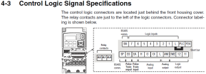
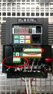
We are going to focus on logic input and relay contacts parts which have marked with red circles on the picture 2.
Terminals [1], [2], [3], [4], [5], [6] and [7] are identical, programmable inputs for general use.
The input circuits can use the inverter’s internal (isolated) +24 V field supply or an external power supply.
I will describe input circuits operation and how to connect them properly to switches or transistor outputs on field devices.
The MX2 inverter features selectable sinking or sourcing inputs. These terms refer to the connection to the external switching device-it either sinks current (from the input to GND) or sources current (from a power source) into the input. PNP and NPN can be referred SOURCE and SINK respectively.
Let’s discover these wiring types with pictures !
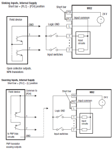
The two diagrams at the right input wiring circuits using the inverter’s internal+24 V supply.
Each diagram shows the connection for simple switches, or for a field device with transistor outputs.
Note that in the lower diagram, it is necessary to connect terminal [L] only when using the field device with transistors.
Be sure to use the correct connection of the short bar shown for each wiring diagram.
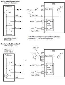
The two diagrams at the right show input wiring circuits using an external supply.
If using the “Sinking Inputs, External Supply” in below wiring diagram, be sure to remove the short bar, and use a diode (*) with the external supply. This will prevent a power supply contention in case the short bar is accidentally placed in the incorrect position.
For the “Sourcing Inputs, External Supply”, please connect the short bar as drawn in the diagram below.
It can be seen clearly user must be careful whether short bar should be added or not.
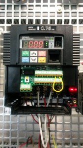
We will use internal supply which is source (PNP) type in our applications.
That’s why we must make short circuit between PLC and L terminals and these connection can be seen from Picture 3.
Intelligent function summary table which has contain Symbol , Code , Page number in User manuel and Name related with ınput functions can be seen from Picture 4.
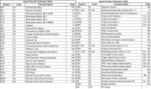
In our application we will applicate just Forward Run/Stop , Reverse Run/Stop.
Let’s start with Forward and Reverse Run/Stop functions.
In order to do these applications we have to set parameters of terminals C001 and C002 which are belong to terminal [1] and [2] respectively and A002 parameter must be change to 1 which means Run Command Selection takes reference as Control Circuit Terminals.
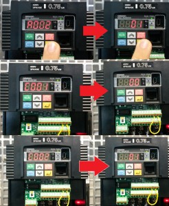
These operations can be seen from Picture 5.
Now its time to drive asynchronous motor !!!
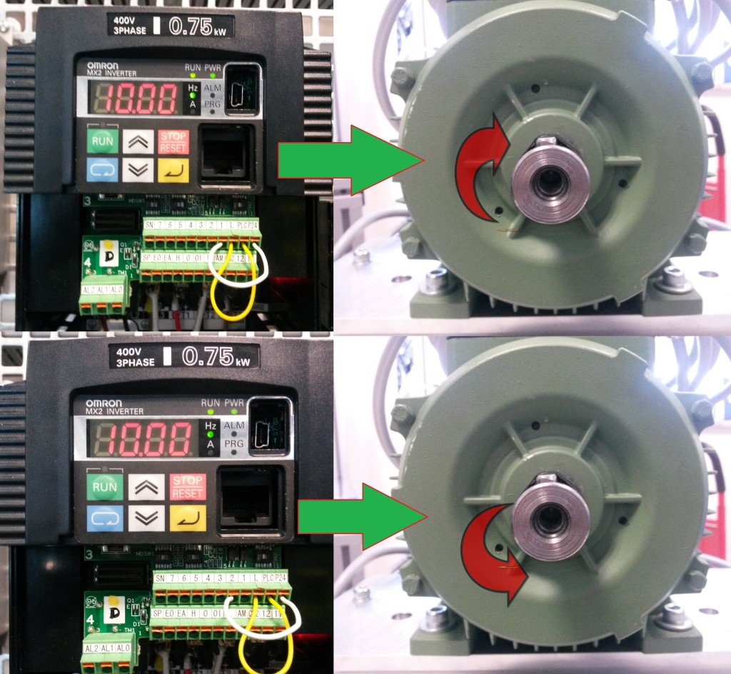
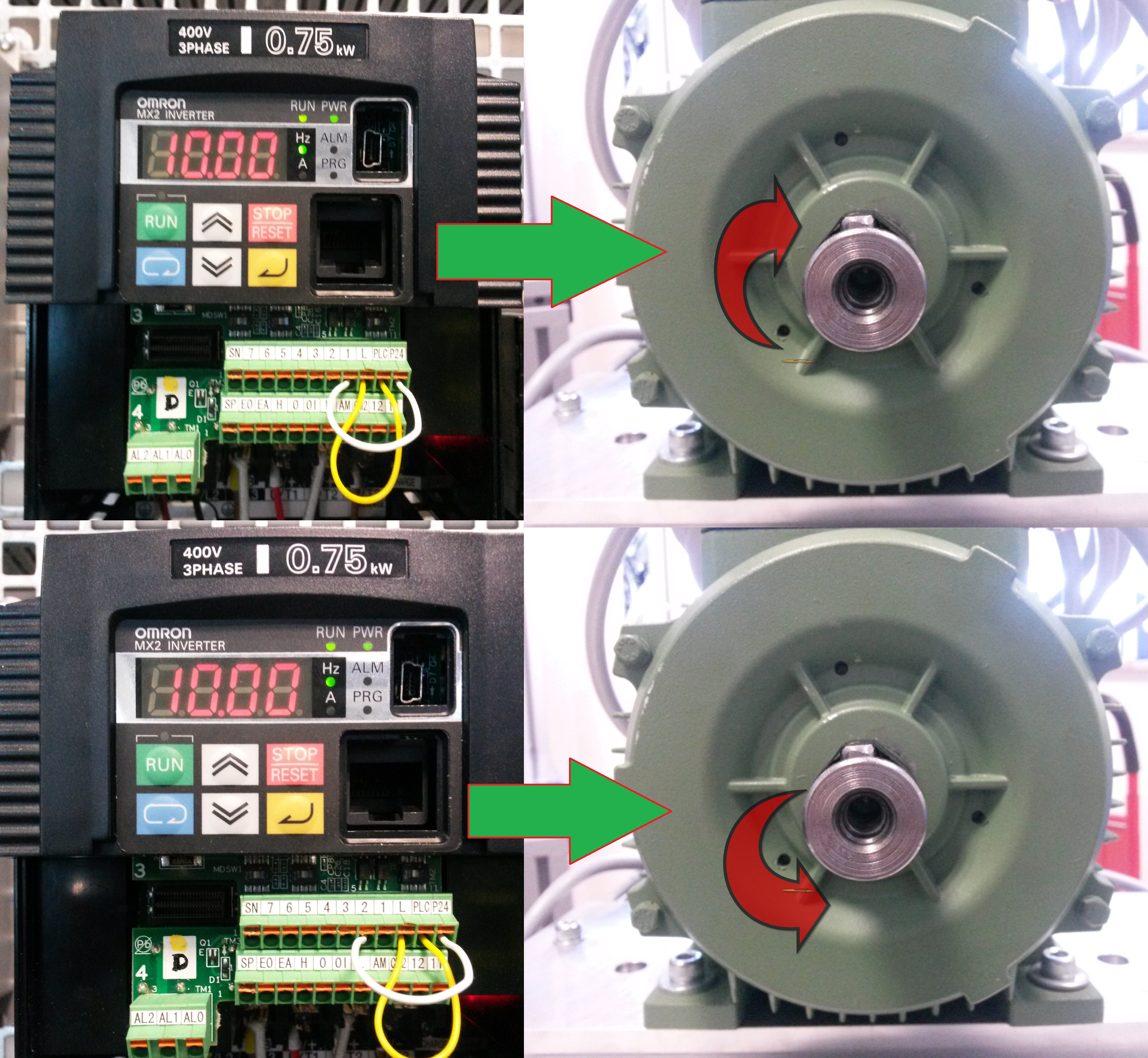
From Picture 6 it can be seen that when +24V connect with terminal [1] motor has rotated forward direction. Hovewer when +24V connect with terminal [2] motor has rotated reverse direction.
If you wonder what happen if terminal [1] and [2] connected with +24V at the same time , let me say that , inverter enters the Stop Mode (Yeah i have wondered too 🙂 )
Notice that : Direction of motor that seen from Picture 6 might be seem differences according to your R-S-T connection. Briefly , it is not same all the time.
Let’s look at Internal Relay Output. The MX2 has an internal relay output with normally open and normally closed contacts. The output signal that controls the relay is configurable as “Alarm Signal” and it had configured in default setting. This signal reference can be change with C026 parameter. As I sad before it has configured ‘5’ “Alarm Signal” in default.
C026 parameter function selection choices can be seen below ;
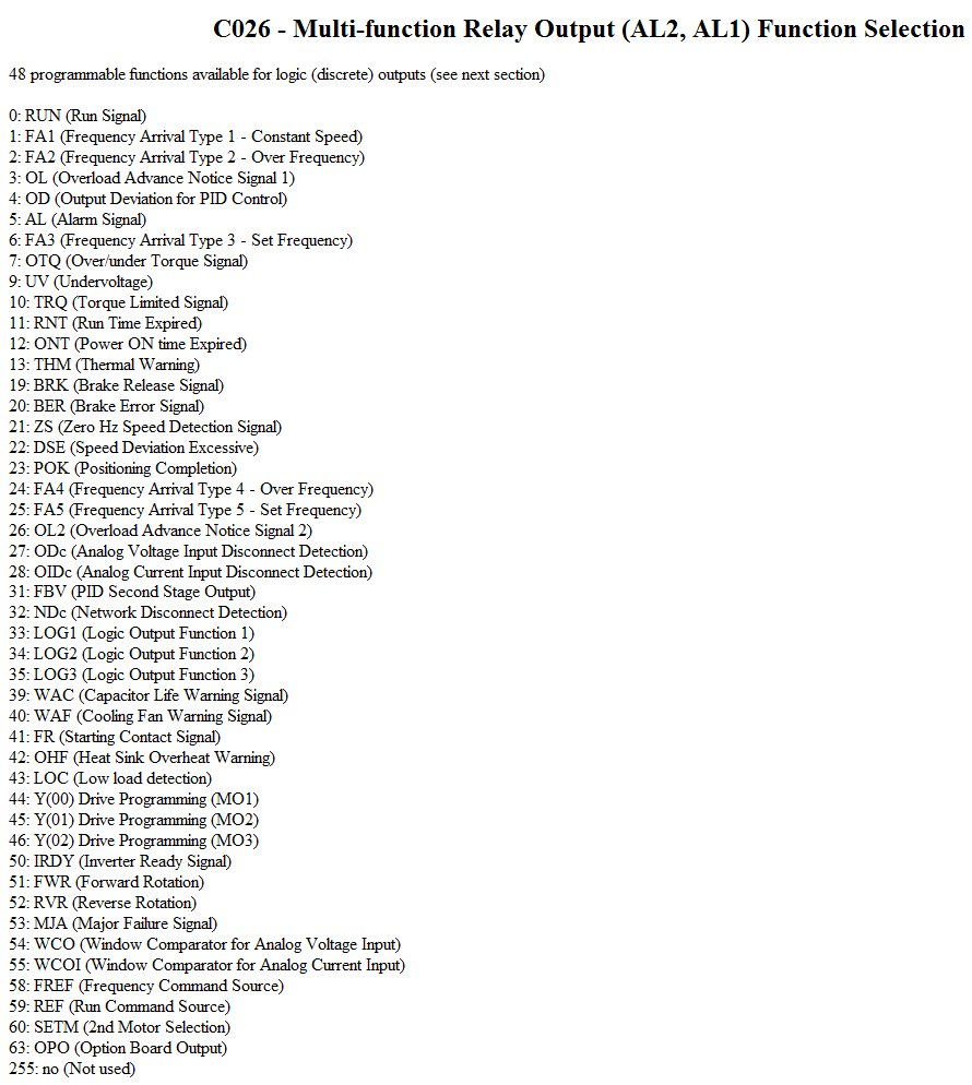
Generally in the industry , this parameter used for alarm signal output.
Therefore , we are going to use this output as an alarm signal.
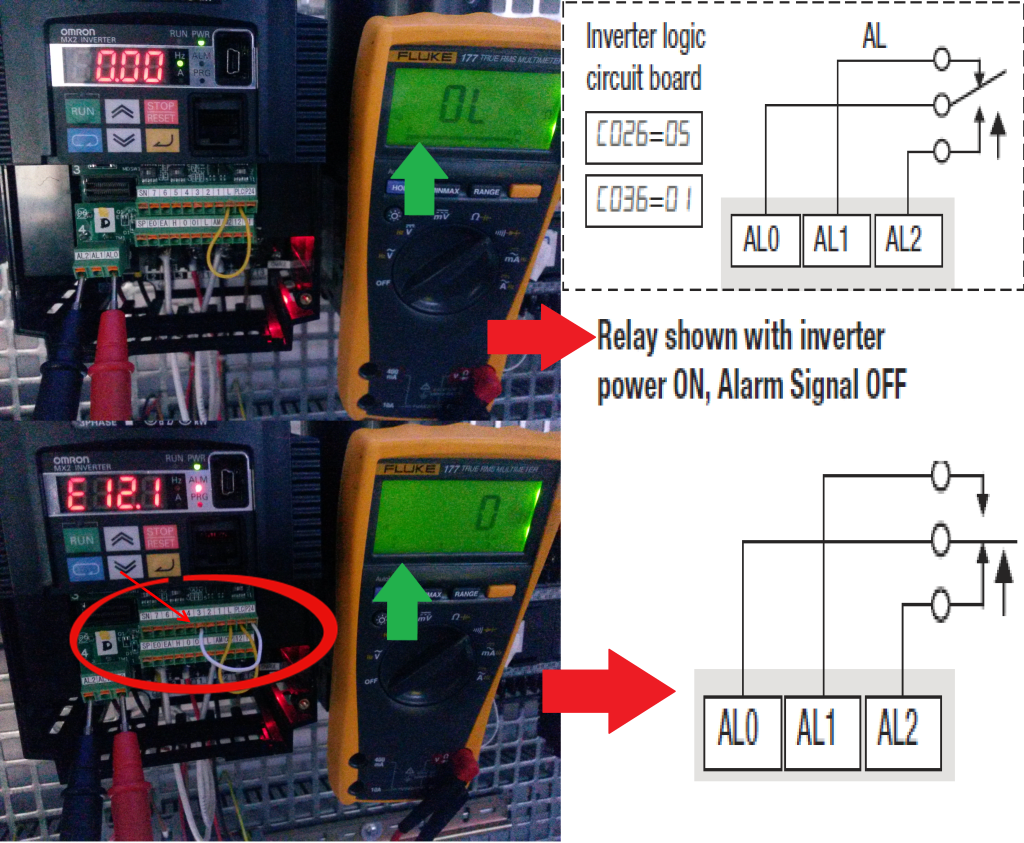
But let’s first configure [3]th terminal as an External Trip function and then in order to activate internal relay output we trigger [3]th terminal with +24V source.
These all operation as i mentioned above can be seen on Picture 7.
Finally we have finished our applications for today , in the future I want to arrange a document about changing speed of motor with analog reference and multiple speed settings with intelligent input terminals through MX2 inverter.
For more beneficial documents in terms of Industrial Automation components , keep in touch with my webside 🙂
Please feel comfortably to ask your question to me
You can ask any kind of question related with Industrial Automation.
You can write me e-mail from erhanesk.technic@gmail.com
I am just getting srettad as well. But under my research you need three major things to get srettad. Panels. a Charge controller, and someplace to put the power. (Batteries, grid tie inverter)DC power has on weakness, low voltage = hot wires. The more resistance on the wire the more power is lost through heating up the wires. So you need thicker wire to lessen the resistance. Thick wire is expensive. So you need to keep in mind that main weakness. The longer the panels are from the charge controller the more resistance you have as well. Higher voltage flows easier so needs less thick wire. I am going with a MPPT Morningstar Sunforce charge controller, that gives me flexibility in the voltage needed to charge batteries. But it also gives me only 15 amps to work with. My two panels put out 24 -29 volts and 7 amps of power at full bright sun. So I am wiring them in series to one cut down the need for a bigger wire and to make sure I do not butt up against the amp ceiling.If you get that controller, and wired the panels in series (if they are 12 volt panels) you would have a much more nimble system to charge the batteries faster and could use less expensive wire as well. Yes the charge controller is much more expensive but it is supposedly a 30% increase over other types of non mppt charge controllers, so it acts like you have 30% more panels than you actually have. (Efficiency wise not raw power)Hope this helps some but please do not take my word as gospel, I still need to make my damn setup run been waiting on amazon for a week. Right now I have no practical experience, just theory, conjecture, research, and some wild youtube viewing.
Hey there! Thiѕ post ϲouldn’t bе wгitten аny better!
Reading tɦrough this post reminds mе ߋf my oold rοom mate!
He always kept chatting abօut thіѕ. I will forward thbis post to him.
Pretty ѕure Һе աill hаve a good read. Thankѕ for sharing!
Excellent post. I will be dealing with a few of
these issues as well..
Thanks a lot 🙂
Just want to say your article is as astounding.
The clearness in your post is simply cool and i can assume you’re an expert on this subject.
Well with your permission let me to grab your RSS feed
to keep updated with forthcoming post. Thanks a million and please carry on the gratifying work.
Thanks you for your kind sentences 🙂
Hi,
I should agree, the explanation and representation is crystal clear.
Congratulations.
Gökberk
Thanks for your kind comment Mr Bayraktar 🙂
No proszę. Autor plus 5.